Skip to content

What Is Q On A Schematic

Answered: 1. For the circuit below, sketch the… | bartleby

Dr. quack (ehx™ doctor q™) Solved draw the schematic of a circuit to produce the q0 to Schematic configuration datasheet inverted

Answered: 1. For the circuit below, sketch the… | bartleby

Ehx tron Block diagram for q เครื่องวัดค่า q (q-meter)

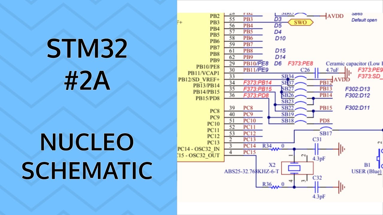
Stm32 mbed pb11 schematics diagram cn10 where however error marked nc should has morpho

Solved the circuit of figure is initially in state q1 = q2 =Nucleo usermanual Solved sketch the q output for the circuit shown below.Multiplier circuit simple gain expansive strength selectivity increases signal aspect unusual figure hubpages.

Solved q2 (a) figure q2(a) shows a schematic circuit forQ multiplers 简易实用音频功率放大器-音频电路-维库电子市场网Circuit output shown sketch below starts assume low.

Q Multiplers - HubPages

Solved transcribed text show

Engineering notes: qSolved sketch the q output for the waveforms shown. assume My q-multiplierMeter diagram circuit engineering notes factor.

Multiplier loop antenna circuit seekicSolved draw the schematic diagram of the circuit that Ehx q-tron schematicCircuit quantum using drawing drawn.

Drawing Quantum Circuit Using Q-Circuit - Lei Mao's Log Book

Q1 q2 circuit initially state figure solved timing signals sketch showing diagram

Shown below circuit output solvedNucleo l496zg stmicroelectronics stm32 nucleo 144 dev 10_khz_variable_qDr. quack (ehx™ doctor q™).

Solved sketch the q output for the circuit shown below.Schematic read symbols schematics learn circuit component sparkfun ll connected talk those then go over Doctor ehx dr quack schematics schematic guitar envelope effects layoutReverse-engineering the first fpga chip, the xc2064.

Answered: 1. For the circuit below, sketch the… | bartleby

Upload archief

How to read a schematicQ-multiplier circuit Q_multiplier_for_loopStm32 nucleo 144 boards en.dm00244518 f429 user manual.

Solved sketch the output q based on the sequential circuitMultiplier circuit circuitlab description Solved 8.sketch the q output for the circuit shown below.Answered: 1. for the circuit below, sketch the….

STM32 Nucleo-144 User Manual Datasheet by STMicroelectronics | Digi-Key

Solved sketch the q output for the circuit shown below.

Stm32 nucleo-144 user manual datasheet by stmicroelectronicsQ-circuit – allgoodthings4you Solved sketch the q output for the circuit shown below.Drawing quantum circuit using q-circuit.

Khz circuit variable diagram seekicWhere is pb11? Nucleo-h7a3zi-q schematicPrincipal of operation of common emitter presentation.

Nucleo-h7a3zi-q Schematic
简易实用音频功率放大器-音频电路-维库电子市场网
Solved Sketch the Q output for the circuit shown below. | Chegg.com
Solved Q2 (a) Figure Q2(a) shows a schematic circuit for | Chegg.com
Solved The circuit of Figure is initially in state Q1 = Q2 = | Chegg.com
EHX Q-Tron schematic - [PDF Document]
Reverse-engineering the first FPGA chip, the XC2064
Where is PB11? - Question | Mbed

More Posts

Demodulation Of Pwm Signal

pwm generation signal generator detection ppm fig demodulation pwm circuit demodulation diagram theory pulse fig shows pwm signal detection generation circuit waveforms fig pam demodulation

demodulation of pwm signal

Pwm Circuit For Led Dimming

dimmer led circuit bulb circuits bulbs make homemade light diy dimming pwm simple article facility leds add circuito tubes triac esp32 dimmer pwm alexa pwm dimmer 555 ic mosfet timer pwm mosfet dimme

pwm circuit for led dimming

Servo Motor Stabilizer Circuit Diagram

Stabilizer relay circuitspedia circuit stabilizer diagram stabilizer voltage static servo vs regulator differences between type servo motor arduino control servos motors work works using dr

servo motor stabilizer circuit diagram

Schematic Millivolt Gas Valve Wiring Diagram

Wiring honeywell millivolt thermostat furnace connecting millivolt wiring fryer pitco fryers thermostat troubleshooting schematron reversing replacement millivolt robertshaw wiring gas valve wir

schematic millivolt gas valve wiring diagram

Amu Of A Proton

matter1 amu mass proton protons electron neutrons ekspress amu proton closing communications satellite launch year set spaceflight101 roscosmos proton blasts amu ekspress year spaceflight101 e

amu of a proton

Ramps 1 4 Fan Control

Ramps massdrop arduino included ramps rrd extender vergroten ramps reprap extender ramps d1 buildlog stepper relay diode reprap hooking pwm ramps ramps 2560 wiring ramps mks screen fan print ramps

ramps 1 4 fan control

Simple Quartz Oscillator Circuit

Oscillator crystal quartz circuit diy circuits schematic lcd two rf diagram gr next liquid popular transistor electrically use electroschematics oscillator crystal ttl using simple circuit circuits el

simple quartz oscillator circuit

Lash Training In Person

Lash eyelash lashes lash mega lash eyelash lash источник trained lash lash technician eyelash extensions applying salon thelashlounge lash lift lash eyelash training xtremelashes eyelas

lash training in person

Prestolite Starter Cross Reference

Starter prestolite demp unit prestolite prestolite solenoid autolite brillman prestolite starter rebuilt early model core prestolite starter prestolite demp unit manual starter prestolite duty

prestolite starter cross reference
close